

M1 ASSEMBLY GUIDE
Detailed instructions to build your own M1.
If you would prefer to follow along in video form, check out the previous live streams on the MatterRay Youtube channel
1.00 | Introduction
1.01 - Tools
1.02 - Skills
2.00 | Parts
2.01 - 3D Printed
2.02 - Stereo Camera
2.03 - USB-C to Micro-B
2.04 - 40mm Ring LEDs
2.05 - Switch
2.06 - Single Line Laser
2.07 - 11 Line Laser
2.08 - 11 Line Laser DOE
2.09 - Boost Converter
2.10 - Buck Converter
2.11 - Connector Block
2.12 - Fan
2.13 - Heatsinks
2.14 - Screws
2.15 - Cable
2.16 - USB-C to USB-A
2.17 - USB Split Power
2.18 - USB Power Meter
2.19 - Marker Dots
2.20 - Calibration Board
3.00 | Electronics Assembly
3.01 - LED Heatsinks
3.02 - Laser DOE
3.03 - LED Wires
3.04 - Prep Wires
3.05 - Fan and Laser Wires
3.06 - USB Connectors
3.07 - Buck Converter
3.08 - Wire Boost and Buck
3.09 - Switch
3.10 - Grounds Together
4.00 | Adjust Electronics
4.01 - Test Setup
4.02 - Focus the Cameras
4.03 - Focus the Lasers
4.04 - Set LED Current
4.05 - Final Check
4.06 - Prep for Assembly
5.00 | Body Assembly
5.01 - Fan Into Lid
5.02 - Lasers Into Lid
5.03 - Cameras Into Base
5.04 - LEDs Into Base
5.05 - Switch
5.06 - Boost and Buck
5.07 - USB
5.08 - Top Cable Clamp
5.09 - Check Operation
5.10 - Align Lasers
5.11 - Fit the Lid
5.12 - Check Airflow
1
The M1 is designed to be as simple as possible to assemble for makers and tinkers, learning new skills or building veterans. The body is designed for FDM 3D printing fitting into a standard 200x200mm build plate with the option for designed supports making removal significantly easier on older or low end printers.

1.00 | Introduction
The M1 is designed to be as simple as possible to assemble for makers and tinkers, learning new skills or building veterans. The body is designed for FDM 3D printing fitting into a standard 200x200mm build plate with the option for designed supports making removal significantly easier on older or low end printers.
1.01 | Tools
You will need the following tools: • FDM 3D Printer and cleanup tools • Soldering Iron and solder • Small wire strippers or side cutters or scissors or craft knife • Philips #2 long shaft screwdriver • Phillips #3 screwdriver • Ruler
1.01
You will need the following tools: • FDM 3D Printer and cleanup tools • Soldering Iron and solder • Small wire strippers or side cutters or scissors or craft knife • Philips #2 long shaft screwdriver • Phillips #3 screwdriver • Ruler
1.02 | Skills
Skills required: • 3D printing knowhow, Download, slice and print the parts and guides • Soldering. This is a pretty good project to learn to solder on if you are new as it is soldering wires together or onto relatively large pads on the circuit boards. • Small wires. The M1 is assembled with small thin wires so some finess is required to strip the insulating plastic off without cutting through the wire. As they are so small standard large wire strippers cannot be used.
1.02
Skills required: • 3D printing knowhow, Download, slice and print the parts and guides • Soldering. This is a pretty good project to learn to solder on if you are new as it is soldering wires together or onto relatively large pads on the circuit boards. • Small wires. The M1 is assembled with small thin wires so some finess is required to strip the insulating plastic off without cutting through the wire. As they are so small standard large wire strippers cannot be used.
2
Parts required: • 3D printed parts • Stereo camera • USB-C to Mini USB R/A • 40mm LED rings • Switch • Fan • Single line laser • 11 line laser • Boost converter • Buck converter • 4 pin rising clamp terminal • Screws • Heat shrink or electrical tape • USB C to USB A cable • USB power meter • Marker dots • Calibration board Total parts cost is a little over $200usd as of mid 2023
2.00 | Parts
Parts required: • 3D printed parts • Stereo camera • USB-C to Mini USB R/A • 40mm LED rings • Switch • Fan • Single line laser • 11 line laser • Boost converter • Buck converter • 4 pin rising clamp terminal • Screws • Heat shrink or electrical tape • USB C to USB A cable • USB power meter • Marker dots • Calibration board Total parts cost is a little over $200usd as of mid 2023
2.01 | 3D Printed
If you are able this should be printed from ABS as it has lower thermal expansion which will help with accuracy, especially for longer scanning sessions. If you do not have the enclosure required for ABS, PETG is the next preferable otherwise PLA has worked suitably. First print the assembly guide. Try a screw in each of the switch and buck/boost clamp to confirm the hole sizes are correct. The screws should thread in fully with some force but not so much required that there is risk of stripping the head or snapping the screw. Once confirmed go ahead and print the remaining parts. If the tolerances require modification edit the original design files to a specification that suits your printer. Files are available in the downloads page.
The files are split into 3 groups:
• Assembly Guide
• Main body
• lid
• 2x Camera screw guides
• Boost/Buck Holder
• Boost/Buck Holding clip
• Boost/Buck Wire clamp
• Upper wire clamp
• Switch clamp
Once printed test fit the lid onto the body and clearance any tight fitting areas to they fit together with no force.
2.01
If you are able this should be printed from ABS as it has lower thermal expansion which will help with accuracy, especially for longer scanning sessions. If you do not have the enclosure required for ABS, PETG is the next preferable otherwise PLA has worked suitably. First print the assembly guide. Try a screw in each of the switch and buck/boost clamp to confirm the hole sizes are correct. The screws should thread in fully with some force but not so much required that there is risk of stripping the head or snapping the screw. Once confirmed go ahead and print the remaining parts. If the tolerances require modification edit the original design files to a specification that suits your printer. Files are available in the downloads page.
The files are split into 3 groups:
• Assembly Guide
• Main body
• lid
• 2x Camera screw guides
• Boost/Buck Holder
• Boost/Buck Holding clip
• Boost/Buck Wire clamp
• Upper wire clamp
• Switch clamp
Once printed test fit the lid onto the body and clearance any tight fitting areas to they fit together with no force.
2.02 | Stereo Camera
The core of the M1 is the stereo camera. The cameras are synchronous meaning both cameras take pictures at the same time. We use this model of camera as it is low cost, commonly available and can have low exposure times preventing blurry frames.
Supplier I have purchase from: https://www.aliexpress.com/item/1005006006917576.html
Search term: 2mp usb stereo synchronization camera
Spec: 3.9mm non distortion lenses, 10cm FFC cable

2.02
The core of the M1 is the stereo camera. The cameras are synchronous meaning both cameras take pictures at the same time. We use this model of camera as it is low cost, commonly available and can have low exposure times preventing blurry frames.
Supplier I have purchase from: https://www.aliexpress.com/item/1005006006917576.html
Search term: 2mp usb stereo synchronization camera
Spec: 3.9mm non distortion lenses, 10cm FFC cable
2.03 | USB-C to Micro-B
The internal power and data link. Ensure you purchase with the correct orientation of Mini USB. Also recommending buying a couple if you're not experienced with sripping smaller wires.
Supplier I have purchase from: https://www.aliexpress.com/item/32948861250.html
Search term: 90 degree angle Type-C Female To Micro-B
Spec: Left Angle

2.03
The internal power and data link. Ensure you purchase with the correct orientation of Mini USB. Also recommending buying a couple if you're not experienced with sripping smaller wires.
Supplier I have purchase from: https://www.aliexpress.com/item/32948861250.html
Search term: 90 degree angle Type-C Female To Micro-B
Spec: Left Angle
2.04 | 40mm Ring LEDs
Used to evenly illuminate the marker dots the leds fit around each of the cameras. These have rather small solder pads so the supplier linked below has agreed to pre-solder the correct wire for us. Though they have been supplying it in the wrong size, so you will need purchase the wire spec'd below as well.
Supplier I have purchase from: https://www.aliexpress.com/item/1005005674711441.html
Search term: 12v ring led 40mm
Spec: 40mm 4W with 25cm 26awg Wire, 1mm OD sheathing (2x required)

2.04
Used to evenly illuminate the marker dots the leds fit around each of the cameras. These have rather small solder pads so the supplier linked below has agreed to pre-solder the correct wire for us. Though they have been supplying it in the wrong size, so you will need purchase the wire spec'd below as well.
Supplier I have purchase from: https://www.aliexpress.com/item/1005005674711441.html
Search term: 12v ring led 40mm
Spec: 40mm 4W with 25cm 26awg Wire, 1mm OD sheathing (2x required)
2.05 | Switch
The 4 position slide switch is used to select each of the scanners modes: Off, Lights on, Lights + single line, Lights + multi line
Supplier I have purchase from: https://www.aliexpress.com/item/1005004678559173.html
Search term: 10Pcs SS-24E04 2P4T
Slide Switch Spec: None

2.05
The 4 position slide switch is used to select each of the scanners modes: Off, Lights on, Lights + single line, Lights + multi line
Supplier I have purchase from: https://www.aliexpress.com/item/1005004678559173.html
Search term: 10Pcs SS-24E04 2P4T
Slide Switch Spec: None
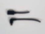
2.06 | Single Line Laser
30mw single line laser for difficult to scan areas
Supplier I have purchase from: https://www.aliexpress.com/item/1005001270080781.html
Search term: D12x45 focusable 650nm laser
Spec: 30mw Line - 60 degree

2.06
30mw single line laser for difficult to scan areas
Supplier I have purchase from: https://www.aliexpress.com/item/1005001270080781.html
Search term: D12x45 focusable 650nm laser
Spec: 30mw Line - 60 degree
2.07 | 11 Line Laser
100mw laser, We will replace the line element with the 11 line DOE
Supplier I have purchase from: https://www.aliexpress.com/item/1005001270080781.html
Search D12x45 focusable 650nm laser
Spec: 100mw Line - 60 degree
2.07
100mw laser, We will replace the line element with the 11 line DOE
Supplier I have purchase from: https://www.aliexpress.com/item/1005001270080781.html
Search D12x45 focusable 650nm laser
Spec: 100mw Line - 60 degree
2.08 | 11 Line Laser DOE
The DOE(defractive optical element) that displays the 11 line pattern
Supplier I have purchase from: https://www.aliexpress.com/item/1005005170193591.html
Search 11 parallel lines DOE
Spec: none

2.08
The DOE(defractive optical element) that displays the 11 line pattern
Supplier I have purchase from: https://www.aliexpress.com/item/1005005170193591.html
Search 11 parallel lines DOE
Spec: none
2.09 | Boost Converter
The mini boost converter takes in the ~5v from the USB and boosts it to 12v for the fan and leds. Ensure you purchase the correct output voltage.
Supplier I have purchase from: https://www.aliexpress.com/item/1005002858417858.html
Search term: Mini DC-DC Boost Step Up Converter
Spec: Output set to 12v

2.09
The mini boost converter takes in the ~5v from the USB and boosts it to 12v for the fan and leds. Ensure you purchase the correct output voltage.
Supplier I have purchase from: https://www.aliexpress.com/item/1005002858417858.html
Search term: Mini DC-DC Boost Step Up Converter
Spec: Output set to 12v
2.10 | Buck Converter
The buck converter is used to restrict the amount of power used by the leds so they don't overpower the usb port or overheat. This would normally be done with a constant current driver but there are no suitable modules available that give any advantage over using a constant voltage.
Supplier I have purchase from: https://www.aliexpress.com/item/1005004587442138.html
Search term: Mini360 Buck
Spec: none

2.1
The buck converter is used to restrict the amount of power used by the leds so they don't overpower the usb port or overheat. This would normally be done with a constant current driver but there are no suitable modules available that give any advantage over using a constant voltage.
Supplier I have purchase from: https://www.aliexpress.com/item/1005004587442138.html
Search term: Mini360 Buck
Spec: none
2.11 | Connector Block
So the leds can be disconnect for complete disassembly
Supplier I have purchase from: https://www.aliexpress.com/item/1005004679967893.html
Search term: KF128 4 pin
Spec: 4 pin

2.11
So the leds can be disconnect for complete disassembly
Supplier I have purchase from: https://www.aliexpress.com/item/1005004679967893.html
Search term: KF128 4 pin
Spec: 4 pin
2.12 | Fan
The lasers, camera modules and leds all cause heat we need to get rid of. A 12v fan is used as it flows much more air than a 5v version and the 12v from the boost converter is much more consistent than the 5v input from the usb. I also recommend a dual ball bearing fan as it spins a little faster and should be longer lasting than oil bearing.
Supplier I have purchase from: https://www.aliexpress.com/item/32810618231.html
Search term: DC 12V dual ball bearings 30x10mm fan
Spec: DC 12v

2.12
The lasers, camera modules and leds all cause heat we need to get rid of. A 12v fan is used as it flows much more air than a 5v version and the 12v from the boost converter is much more consistent than the 5v input from the usb. I also recommend a dual ball bearing fan as it spins a little faster and should be longer lasting than oil bearing.
Supplier I have purchase from: https://www.aliexpress.com/item/32810618231.html
Search term: DC 12V dual ball bearings 30x10mm fan
Spec: DC 12v
2.13 | Heatsinks
Small heatsinks for the back of the leds give a larger surface area to help dissipate heat.
Supplier I have purchase from: https://www.aliexpress.com/item/4000303533546.html
Search term: heatsink 8.8*8.8*5mm with thermal double sided tape
Spec: Black (8x required)

2.13
Small heatsinks for the back of the leds give a larger surface area to help dissipate heat.
Supplier I have purchase from: https://www.aliexpress.com/item/4000303533546.html
Search term: heatsink 8.8*8.8*5mm with thermal double sided tape
Spec: Black (8x required)
2.14 | Screws
Two sizes of self tapping screws are used, Small M1.7x12mm for the electronics as the camera module uses 2mm mounting holes and larger M3x12mm for securing the lid
Supplier I have purchase from: https://www.aliexpress.com/item/1005003966275108.html
Search term: round head self tapping screw
Spec: M1.7x12mm, M3x12mm (Get at least 20pcs of each)

2.14
Two sizes of self tapping screws are used, Small M1.7x12mm for the electronics as the camera module uses 2mm mounting holes and larger M3x12mm for securing the lid
Supplier I have purchase from: https://www.aliexpress.com/item/1005003966275108.html
Search term: round head self tapping screw
Spec: M1.7x12mm, M3x12mm (Get at least 20pcs of each)
2.15 | Cable
This should not be required if you purchase the 40mm leds with cable pre-soldered as the excess will complete the assembly
Supplier I have purchase from: https://www.aliexpress.com/item/1005004167126040.html
Search term: Copper wire 26 awg pvc insulated
Spec: 5meters each of black 26awg and red 26awg

2.15
This should not be required if you purchase the 40mm leds with cable pre-soldered as the excess will complete the assembly
Supplier I have purchase from: https://www.aliexpress.com/item/1005004167126040.html
Search term: Copper wire 26 awg pvc insulated
Spec: 5meters each of black 26awg and red 26awg
2.16 | USB-C to USB-A
The main cable to connect to your pc. This must be a standard cable as fast charge cables do not seem to support such high current at 5v. The camera is only USB 2.0 but from my testing standard usb-c cables have the lowest resistance allowing for longer cable lengths and higher power draw for the lights.
Supplier I have purchase from: https://www.aliexpress.com/item/4001161628046.html
Search term: USB Type C Cable 3A fast charging
Spec: PVC Shell Black, 3 meters

2.16
The main cable to connect to your pc. This must be a standard cable as fast charge cables do not seem to support such high current at 5v. The camera is only USB 2.0 but from my testing standard usb-c cables have the lowest resistance allowing for longer cable lengths and higher power draw for the lights.
Supplier I have purchase from: https://www.aliexpress.com/item/4001161628046.html
Search term: USB Type C Cable 3A fast charging
Spec: PVC Shell Black, 3 meters
2.17 | USB Split Power
We draw more power than the standard usb spec allows for. On most computers they will happily put out the extra power but in case yours is not willing a split power cable will allow allow you to draw power from two usb ports
Supplier I have purchase from: https://www.aliexpress.com/item/4000316879295.html
Search term: USB 3.0 Female to Dual USB Male Extra Power
Spec: none

2.17
We draw more power than the standard usb spec allows for. On most computers they will happily put out the extra power but in case yours is not willing a split power cable will allow allow you to draw power from two usb ports
Supplier I have purchase from: https://www.aliexpress.com/item/4000316879295.html
Search term: USB 3.0 Female to Dual USB Male Extra Power
Spec: none
2.18 | USB Power Meter
This is used during setup to adjust the lights to the maximum allowable power draw without overpowering the usb port, overpowering the boost converter or running the lights too hot.
Supplier I have purchase from: https://www.aliexpress.com/item/4000037898130.html
Search term: USB Current Voltage Capacity Tester
Spec: none

2.18
This is used during setup to adjust the lights to the maximum allowable power draw without overpowering the usb port, overpowering the boost converter or running the lights too hot.
Supplier I have purchase from: https://www.aliexpress.com/item/4000037898130.html
Search term: USB Current Voltage Capacity Tester
Spec: none
2.19 | Marker Dots
The marker dots used are 10mm/5mm non reflective dots. The same used by the revopoint pop scanners. These are low cost when bought in bulk, can be detected from a reasonable distance and allow for consistent detection.
Supplier I have purchase from: https://www.aliexpress.com/item/1005004918810828.html
Search term: 10,000 Points 3D Scanner Marking Point
Spec: 5mm x 10mm

2.19
The marker dots used are 10mm/5mm non reflective dots. The same used by the revopoint pop scanners. These are low cost when bought in bulk, can be detected from a reasonable distance and allow for consistent detection.
Supplier I have purchase from: https://www.aliexpress.com/item/1005004918810828.html
Search term: 10,000 Points 3D Scanner Marking Point
Spec: 5mm x 10mm
2.20 | Calibration Board
The calibration board is printed onto foam board that is typically used for signage, this is a good compromise between cost and accuracy. As this is a custom design printed onto A3 sized boards you will need to find a local company to do this for you. Check the forum for recommended companies near you or make a post to let other know who has done a good job. The required files can be found in the downloads page here https://www.matterray.com/file-share/bd79c7f7-940b-4c23-8974-12fe735ca0af once you are logged in, Only the 20x20 is required for the M1. If possible have these printed in a matte finish to help prevent reflections from the lights back to the cameras.

2.2
The calibration board is printed onto foam board that is typically used for signage, this is a good compromise between cost and accuracy. As this is a custom design printed onto A3 sized boards you will need to find a local company to do this for you. Check the forum for recommended companies near you or make a post to let other know who has done a good job. The required files can be found in the downloads page here https://www.matterray.com/file-share/bd79c7f7-940b-4c23-8974-12fe735ca0af once you are logged in, Only the 20x20 is required for the M1. If possible have these printed in a matte finish to help prevent reflections from the lights back to the cameras.
3
Once you have printed and purchased the required parts it is time for assembly. This is broken down into two main parts. Wiring the electronics and fitting everything into the body

3.00 | Electronics Assembly
Once you have printed and purchased the required parts it is time for assembly. This is broken down into two main parts. Wiring the electronics and fitting everything into the body
3.01 | LED Heatsinks
Using the led guide area of the assembly jig: • Remove the adhesive backing covers from 4 of the heat sinks and place them, adhesive up, into the 4 spots in the guide. • Retrieve a pre-wired ring led, align it as shown with the dimple in the guide and press it onto the heat sinks so they are securely adhered in place. • Repeat for the second ring led. On the back of the lights label one A and the other B


3.01
Using the led guide area of the assembly jig: • Remove the adhesive backing covers from 4 of the heat sinks and place them, adhesive up, into the 4 spots in the guide. • Retrieve a pre-wired ring led, align it as shown with the dimple in the guide and press it onto the heat sinks so they are securely adhered in place. • Repeat for the second ring led. On the back of the lights label one A and the other B
3.02 | Laser DOE
To fit the 11 line DOE to the 100mw laser, taking care not to get dust on the lens or inside the laser:
• Unscrew the lens from the laser
• Use the laser lens separating tools to separate the cap from the lens and remove the single line lens
• Stack the 3D printed spacer and 11 line laser DOE as shown and re fit the cap to the lens. Try to avoid touching the DOE top and bottom faces.
• Lightly tighten the cap back on to the lens so the spacer and DOE do not rattle.
• Re-fit the lens to the laser body.


3.02
To fit the 11 line DOE to the 100mw laser, taking care not to get dust on the lens or inside the laser:
• Unscrew the lens from the laser
• Use the laser lens separating tools to separate the cap from the lens and remove the single line lens
• Stack the 3D printed spacer and 11 line laser DOE as shown and re fit the cap to the lens. Try to avoid touching the DOE top and bottom faces.
• Lightly tighten the cap back on to the lens so the spacer and DOE do not rattle.
• Re-fit the lens to the laser body.
3.03 | LED Wires
• Use a ruler to cut the led labeled A's wires to 95mm long and led B's wires to 115mm long. • Strip the end of the wires back 3mm, twist and pre-tin the ends with solder. If you are learning to strip and solder small wires, practice with some of the excess wire cut off of the leds first.

3.03
• Use a ruler to cut the led labeled A's wires to 95mm long and led B's wires to 115mm long. • Strip the end of the wires back 3mm, twist and pre-tin the ends with solder. If you are learning to strip and solder small wires, practice with some of the excess wire cut off of the leds first.
3.04 | Prep Wires
Using the excess wire removed from the ring leds, separate the red and black wires. Cut the following lengths • USB to switch - 105mm red - Strip 2mm and 5mm • USB to ground - 85mm black - Strip 2mm and 5mm • Boost to switch - 115mm red - Strip 2mm and 5mm • Boost to ground - 85mm black - Strip 2mm and 5mm • Boost switch hop - 30mm red - Strip 2mm and 5mm • Boost to Buck - 30mm red - Strip 2mm and 5mm • Boost to Buck - 30mm black - Strip 2mm both ends Where you stripped to 2mm long twist the wires and solder the wire. Just twist the ramaingin 5mm stripped ends.


3.04
Using the excess wire removed from the ring leds, separate the red and black wires. Cut the following lengths • USB to switch - 105mm red - Strip 2mm and 5mm • USB to ground - 85mm black - Strip 2mm and 5mm • Boost to switch - 115mm red - Strip 2mm and 5mm • Boost to ground - 85mm black - Strip 2mm and 5mm • Boost switch hop - 30mm red - Strip 2mm and 5mm • Boost to Buck - 30mm red - Strip 2mm and 5mm • Boost to Buck - 30mm black - Strip 2mm both ends Where you stripped to 2mm long twist the wires and solder the wire. Just twist the ramaingin 5mm stripped ends.
3.05 | Fan and Laser Wires
• Cut the fan red wire to 270mm long and the black wire to 160mm long. Strip back 5mm and twist and do not solder • Cut the laser red wire to160mmlong and the black wire to 140mm long. Strip the red wires back 2mm, twist and solder. Strip the black wires back 5mm, twist and do not solder


3.05
• Cut the fan red wire to 270mm long and the black wire to 160mm long. Strip back 5mm and twist and do not solder • Cut the laser red wire to160mmlong and the black wire to 140mm long. Strip the red wires back 2mm, twist and solder. Strip the black wires back 5mm, twist and do not solder
3.06 | USB Connectors
• Cut the wire in two places, 45mm out from USB-C side and 85mm out from Micro-B side • To strip the black outer shielding carefully score around the base and bend the cable over so it splits open. Make additional cuts as needed untill the outer black sheething can be removed. Complete this on both cables. • Strip the 4 wires of each connector back 5mm and twist. • Twist the white wires of each connector together as shown and solder. Repeat for the green wires. Cover the wires with insulation that extends above and below the bare wires. • Holding each connector and evenly twist the white and green wires around each other as shown. They are the USB data lines in what is called a differential pair so they must be kept close to each other to work correctly. • Take both red wires from the USB connectors and the additional USB to switch wire. twist all 3 wires together and solder. Repeat for the black wires and USB to ground wire. • Fold the additional red and black wires up and insulate the connections. Finally secure all the insulation together.


3.06
• Cut the wire in two places, 45mm out from USB-C side and 85mm out from Micro-B side • To strip the black outer shielding carefully score around the base and bend the cable over so it splits open. Make additional cuts as needed untill the outer black sheething can be removed. Complete this on both cables. • Strip the 4 wires of each connector back 5mm and twist. • Twist the white wires of each connector together as shown and solder. Repeat for the green wires. Cover the wires with insulation that extends above and below the bare wires. • Holding each connector and evenly twist the white and green wires around each other as shown. They are the USB data lines in what is called a differential pair so they must be kept close to each other to work correctly. • Take both red wires from the USB connectors and the additional USB to switch wire. twist all 3 wires together and solder. Repeat for the black wires and USB to ground wire. • Fold the additional red and black wires up and insulate the connections. Finally secure all the insulation together.
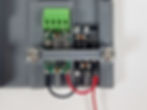
3.07 | Buck Converter
• Fit the buck and boost converters into the assembly jig and fix in place with the hold down clamp. • Pre-tin all 4 pads on the black boost converter and 3 of the pads on the green buck converter as shown. • Retrieve the 4 pin rising clamp terminal block and bend the inner legs out, overtop of and contacting the outer legs. Pre tin both pairs of legs. • Align the terminal block into the jig and solder onto the buck converter starting with the pre-tinned side, and finally the other side as shown


3.07
• Fit the buck and boost converters into the assembly jig and fix in place with the hold down clamp. • Pre-tin all 4 pads on the black boost converter and 3 of the pads on the green buck converter as shown. • Retrieve the 4 pin rising clamp terminal block and bend the inner legs out, overtop of and contacting the outer legs. Pre tin both pairs of legs. • Align the terminal block into the jig and solder onto the buck converter starting with the pre-tinned side, and finally the other side as shown
3.08 | Wire Boost and Buck
• Twist and solder the red wire for between the boost and buck converter and the red wire from the fan together then trim to 2mm long. These can then be soldered onto the boost converter positive (+) output. • Solder the other end of the to the buck converters input and solder the boost converters switch and ground wires to the boost converters input. • Solder the black buck to boost wire onto the boost ground (-) output • Solder both the positive and negitave wires onto the buck converter input • Solder the boost to switch and boost to ground wires onto the boost converter input • Twist the boost positive and switch jumper together and solder. Trim the wires if required so they are ~4mm long


3.08
• Twist and solder the red wire for between the boost and buck converter and the red wire from the fan together then trim to 2mm long. These can then be soldered onto the boost converter positive (+) output. • Solder the other end of the to the buck converters input and solder the boost converters switch and ground wires to the boost converters input. • Solder the black buck to boost wire onto the boost ground (-) output • Solder both the positive and negitave wires onto the buck converter input • Solder the boost to switch and boost to ground wires onto the boost converter input • Twist the boost positive and switch jumper together and solder. Trim the wires if required so they are ~4mm long
3.09 | Switch
• Secure the switch onto the assembly jig with the correct orentation. • On the switch, bend the two pairs of legs together as shown and pre-tin the individual legs and leg pairs. Use the wiring diagram as a guide for the following: • Solder the boost to switch wire onto the paired legs and jumper wire to the single leg • Solder the USB positive wire onto the paired power legs • Solder the single line laser power wire the correct pin • Solder the 11 line laser power wire to the correct pin


3.09
• Secure the switch onto the assembly jig with the correct orentation. • On the switch, bend the two pairs of legs together as shown and pre-tin the individual legs and leg pairs. Use the wiring diagram as a guide for the following: • Solder the boost to switch wire onto the paired legs and jumper wire to the single leg • Solder the USB positive wire onto the paired power legs • Solder the single line laser power wire the correct pin • Solder the 11 line laser power wire to the correct pin
3.10 | Grounds Together
Take the 5 ground wires: • USB ground • Boost ground • Fan ground • Single line laser ground • 11 line laser ground Run them into a group to the left of the laser, twist together and solder. Cover with insulation tape or heat shrink.

3.1
Take the 5 ground wires: • USB ground • Boost ground • Fan ground • Single line laser ground • 11 line laser ground Run them into a group to the left of the laser, twist together and solder. Cover with insulation tape or heat shrink.
4
While all the electronics are accessable we will adjust the focus of the cameras and lasers and the current draw of the LEDs This musnt be preformed on a non conductive surface like a wooden table. To help prevent static shocks dont wear any footwear and avoid carpeted surfaces.
4.00 | Adjust Electronics
While all the electronics are accessable we will adjust the focus of the cameras and lasers and the current draw of the LEDs This musnt be preformed on a non conductive surface like a wooden table. To help prevent static shocks dont wear any footwear and avoid carpeted surfaces.
4.01 | Test Setup
• Ensure the switch is in the off position and the ring leds are not connected • Place the fan in a location that it wont be damaged or do damage when turned on. • Connect the Mini USB right angle into the camera board, plug in the USB-C to USB-A cable, followed by the power meter into your pc's usb3 port. It is prefurable to set this up plugged into the port on the PC you will most likely use for scanning.

4.01
• Ensure the switch is in the off position and the ring leds are not connected • Place the fan in a location that it wont be damaged or do damage when turned on. • Connect the Mini USB right angle into the camera board, plug in the USB-C to USB-A cable, followed by the power meter into your pc's usb3 port. It is prefurable to set this up plugged into the port on the PC you will most likely use for scanning.
4.02 | Focus the Cameras
• Open windows camera viewer to the connected stereo camera • Find a detailed object to focus on and place it 400mm away from the camera lenses • Loosen the focus locking ring on each camera • Twist the camera's lens's to adjust each cameras focus onto the object • Once focused use the lock ring to secure the lens in place. Double check the focus after tightening as it often changes and can take a few tries to get just right • Move the object ~250mm away from the cameras and check the focus. For best results the lens should be kept rotated as counter clockwise (screwed out) as much as possible so 400mm is nearing the maximum focus distance and ~250mm is the closest in focus distance. • The focus distances on each camera should match as close as possible. This is best tested by bringing the object to the close focus limits of the cameras


4.02
• Open windows camera viewer to the connected stereo camera • Find a detailed object to focus on and place it 400mm away from the camera lenses • Loosen the focus locking ring on each camera • Twist the camera's lens's to adjust each cameras focus onto the object • Once focused use the lock ring to secure the lens in place. Double check the focus after tightening as it often changes and can take a few tries to get just right • Move the object ~250mm away from the cameras and check the focus. For best results the lens should be kept rotated as counter clockwise (screwed out) as much as possible so 400mm is nearing the maximum focus distance and ~250mm is the closest in focus distance. • The focus distances on each camera should match as close as possible. This is best tested by bringing the object to the close focus limits of the cameras
4.03 | Focus the Lasers
CAUTION the lasers are bright and may cause eye damage is looked into. So don't, and take note of reflections while scanning. • Set the single line laser up 400mm away from a flat wall • Use the switch to turn the laser on then turn the focus ring so the laser line is as thin as possible at that distance. • Use some tape between the focusing ring and body to keep it in place • Repeat for the 11 line laser


4.03
CAUTION the lasers are bright and may cause eye damage is looked into. So don't, and take note of reflections while scanning. • Set the single line laser up 400mm away from a flat wall • Use the switch to turn the laser on then turn the focus ring so the laser line is as thin as possible at that distance. • Use some tape between the focusing ring and body to keep it in place • Repeat for the 11 line laser
4.04 | Set LED Current
• Disconnect the USB from the PC and set the switch into the off position • Turn the adjustment knob on the buck converter clockwise so the flat edge is aligned with the grey coil, matching the first image • Take care not to run the LED-s for too long as they can overheat without additional airflow. They should never be too hot to touch. • Remove the boost/buck converter clamp, wire each of the LED's into the buck converter using the wiring diagram as a guide and re-seat and secure into the assembly jig with the clamp. • Re-connect the USB to the PC • Open the windows camera viewer so the cameras are operating and ensure the USB current meter is in a visible location and is displaying the current draw • Set the switch on to the last position so the 11 line laser is operating. • Slowly turn the adjustment knob on the buck converter counter clockwise until the LED's start to light up. There is a very small window between the lights starting to illuminate and overpowering the boost converter so turn slowly! • Adjust the knob so, using the USB current meter as a guide, the total current draw is 1.5 amps If you adjust too far it is possible to overload the USB port causing it to shut down. Restarting the PC will typically also re-start the port


4.04
• Disconnect the USB from the PC and set the switch into the off position • Turn the adjustment knob on the buck converter clockwise so the flat edge is aligned with the grey coil, matching the first image • Take care not to run the LED-s for too long as they can overheat without additional airflow. They should never be too hot to touch. • Remove the boost/buck converter clamp, wire each of the LED's into the buck converter using the wiring diagram as a guide and re-seat and secure into the assembly jig with the clamp. • Re-connect the USB to the PC • Open the windows camera viewer so the cameras are operating and ensure the USB current meter is in a visible location and is displaying the current draw • Set the switch on to the last position so the 11 line laser is operating. • Slowly turn the adjustment knob on the buck converter counter clockwise until the LED's start to light up. There is a very small window between the lights starting to illuminate and overpowering the boost converter so turn slowly! • Adjust the knob so, using the USB current meter as a guide, the total current draw is 1.5 amps If you adjust too far it is possible to overload the USB port causing it to shut down. Restarting the PC will typically also re-start the port
4.05 | Final Check
With everything wired you can verify: • When the USB is connected the cameras show up and display in windows camera viewer without • When the switch is set to the off position the lights, lasers and fans are all off • When the switch is set to the 1st position the lights and fan turn on but lasers remain off • When set to the 2nd position the lights and fan remain on and the single line laser turns on • When set to the 3rd position the lights and fan remain on, The single line laser turns off and 11 line laser turns on • There is no flickering, dropouts or any abnormal lines or images displayed by the cameras at any time. • The lights and lasers reamin steadily lit when turned on • The fan may run at slightly different speeds when switching between each light and laser mode but always maintains a high rpm
4.05
With everything wired you can verify: • When the USB is connected the cameras show up and display in windows camera viewer without • When the switch is set to the off position the lights, lasers and fans are all off • When the switch is set to the 1st position the lights and fan turn on but lasers remain off • When set to the 2nd position the lights and fan remain on and the single line laser turns on • When set to the 3rd position the lights and fan remain on, The single line laser turns off and 11 line laser turns on • There is no flickering, dropouts or any abnormal lines or images displayed by the cameras at any time. • The lights and lasers reamin steadily lit when turned on • The fan may run at slightly different speeds when switching between each light and laser mode but always maintains a high rpm
4.06 | Prep for Assembly
• Disconnect the camera and other USBs • Un-wire the ring leds • Un-screw the switch and the boost/buck bracket from the assembly jig

4.06
• Disconnect the camera and other USBs • Un-wire the ring leds • Un-screw the switch and the boost/buck bracket from the assembly jig
5
Lets get it all together!

5.00 | Body Assembly
Lets get it all together!
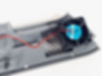
5.01 | Fan Into Lid
Run the fan wire through the groove, Fit the fan orentated as shown to pull air in. Fully thread a small screw in the indicated corner to secure in place


5.01
Run the fan wire through the groove, Fit the fan orentated as shown to pull air in. Fully thread a small screw in the indicated corner to secure in place
5.02 | Lasers Into Lid
• Fit the 11 line laser into the lower position, running the fan wire underneath and running the laser wire through the groove underneath the laser. • Fit the single line laser above so all the wires exit between the two lasers. • Loosely fit the laser clamp with 2x small screws. • Ensure the wires are laid flat against the laser and clamp and the laser wires remain in the groove underneath the laser before tightening the clamp down.


5.02
• Fit the 11 line laser into the lower position, running the fan wire underneath and running the laser wire through the groove underneath the laser. • Fit the single line laser above so all the wires exit between the two lasers. • Loosely fit the laser clamp with 2x small screws. • Ensure the wires are laid flat against the laser and clamp and the laser wires remain in the groove underneath the laser before tightening the clamp down.
5.03 | Cameras Into Base
• Dismantle the stereo camera assembly by un-screwing the standoffs between the camera boards and main board. Then disconnect the white flat FPC cables from the main board by gently sliding both sides of the connector locking tab towards the cable. Once loose the FPC cable can be removed without force • Starting with the B camera (indicated on the front of the camera) Fit a camera screw guide over top and pass 4 small screws through. Working at the top camera position of the main body, pass the FPC cable through and seat the camera into position at the back of the body. Screw all 4 screws into the main body a couple mm then double check the camera and screw guide are fully seated by pressing the screw guide into towards the body. • Complete screwing in the 4 screws taking care to not over tighten. Ensure you maintain pressure on the screw head and only tighten in small rotations ~1/4 turn at a time to prevent stripping the head of the screw. If the screw starts to fail remove and replace it. • Repeat for the A camera at the bottom camera position. • Orientate the main board so the USB connector is on the left, carefully re-insert the FPC cables taking care that they are bottomed out and square into the connector then secure in place by sliding the locking tabs back into their lock position. • Position the main board into the main body and hold in place with a small screw though the main board spacer. • Gently stow the FPC cables into the body as showing taking care not to fold or squish them


5.03
• Dismantle the stereo camera assembly by un-screwing the standoffs between the camera boards and main board. Then disconnect the white flat FPC cables from the main board by gently sliding both sides of the connector locking tab towards the cable. Once loose the FPC cable can be removed without force • Starting with the B camera (indicated on the front of the camera) Fit a camera screw guide over top and pass 4 small screws through. Working at the top camera position of the main body, pass the FPC cable through and seat the camera into position at the back of the body. Screw all 4 screws into the main body a couple mm then double check the camera and screw guide are fully seated by pressing the screw guide into towards the body. • Complete screwing in the 4 screws taking care to not over tighten. Ensure you maintain pressure on the screw head and only tighten in small rotations ~1/4 turn at a time to prevent stripping the head of the screw. If the screw starts to fail remove and replace it. • Repeat for the A camera at the bottom camera position. • Orientate the main board so the USB connector is on the left, carefully re-insert the FPC cables taking care that they are bottomed out and square into the connector then secure in place by sliding the locking tabs back into their lock position. • Position the main board into the main body and hold in place with a small screw though the main board spacer. • Gently stow the FPC cables into the body as showing taking care not to fold or squish them
5.04 | LEDs Into Base
Starting with the B LED (long wire): • Pass the wire through the wireguide below the top camera • Bend the wires on the LED so they pass down through the notch and align the led and wires to the base • Gently press the LED into its seating ring taking care to to dislodge any of the heatsinks • Fit 2x small screws into the screw guide to secure the LED in place. Do not overtighten, only screw so the base of the screw head just squishes the LED PCB Repeat for the lower A LED


5.04
Starting with the B LED (long wire): • Pass the wire through the wireguide below the top camera • Bend the wires on the LED so they pass down through the notch and align the led and wires to the base • Gently press the LED into its seating ring taking care to to dislodge any of the heatsinks • Fit 2x small screws into the screw guide to secure the LED in place. Do not overtighten, only screw so the base of the screw head just squishes the LED PCB Repeat for the lower A LED
5.05 | Switch
• Fit a small screw through the provided hole at the base of the switch position. • Set the switch into the upper on position and pass it into the main body by sliding the top in and then rotating into position • Insert the switch clamp with the leg positioned down into the body and tighten the small screw untill the clamp puts pressure onto the switch and holds it securely in place. • Check the switch operates freely into all 4 positions


5.05
• Fit a small screw through the provided hole at the base of the switch position. • Set the switch into the upper on position and pass it into the main body by sliding the top in and then rotating into position • Insert the switch clamp with the leg positioned down into the body and tighten the small screw untill the clamp puts pressure onto the switch and holds it securely in place. • Check the switch operates freely into all 4 positions
5.06 | Boost and Buck
• Fit the boost and buck PCBs into the 3D printed holder and secure in place by slotting the clip into the grooves • Connect the power and ground from each of the LEDs to the buck output and give a gentle tug test on each wire to ensure it is secured in place • Sit the Buck & Boost assembly into position on top of the camera main board and fit the large cable clamp using 2x small screws so it holdes the lower LED wires underneath and the fan power wire loops under then back over top • Fit the small cable clamp with using a single small screw so it secures the top led wires and fan power wire


5.06
• Fit the boost and buck PCBs into the 3D printed holder and secure in place by slotting the clip into the grooves • Connect the power and ground from each of the LEDs to the buck output and give a gentle tug test on each wire to ensure it is secured in place • Sit the Buck & Boost assembly into position on top of the camera main board and fit the large cable clamp using 2x small screws so it holdes the lower LED wires underneath and the fan power wire loops under then back over top • Fit the small cable clamp with using a single small screw so it secures the top led wires and fan power wire
5.07 | USB
• Slot the USB-C connector into the holder so it bottoms out against the guide rails. Use a large screw in the upper groove to secure the connector in place. If it ramins loose use the next screw position. • Plug in the Micro-B USB connector into the camera main board


5.07
• Slot the USB-C connector into the holder so it bottoms out against the guide rails. Use a large screw in the upper groove to secure the connector in place. If it ramins loose use the next screw position. • Plug in the Micro-B USB connector into the camera main board
5.08 | Top Cable Clamp
• Fit the top cable clamp using 2x small screws so all of the switch and ground wires are clamped down anf the fan power wire loops over then under the clamp


5.08
• Fit the top cable clamp using 2x small screws so all of the switch and ground wires are clamped down anf the fan power wire loops over then under the clamp
5.09 | Check Operation
• Connect the USB to the PC and one again open windows camera viewer. Set the switch to each position and confirm that the cameras operate without fault and the LEDs and lasers perform the same
5.09
• Connect the USB to the PC and one again open windows camera viewer. Set the switch to each position and confirm that the cameras operate without fault and the LEDs and lasers perform the same
5.10 | Align Lasers
With the lid laying flat on a table, square to a vertical reference on a wall: • loosen the laser clamp so the lasers can rotate, taking care to rotate the body and les as one so the laser remains in focus. • Align the laser lines of the single and 11 line modules so they align with the vertical reference on the wall. • Re-tighten the laser clamp. • Re-check that the laser wires are tucked into the guide grooves.


5.1
With the lid laying flat on a table, square to a vertical reference on a wall: • loosen the laser clamp so the lasers can rotate, taking care to rotate the body and les as one so the laser remains in focus. • Align the laser lines of the single and 11 line modules so they align with the vertical reference on the wall. • Re-tighten the laser clamp. • Re-check that the laser wires are tucked into the guide grooves.
5.11 | Fit the Lid
• Fit the lid onto the body taking care so the lid to body wires coil towards the top of the body and no wires get squished. • Use 10x large screws to secure the lid in place


5.11
• Fit the lid onto the body taking care so the lid to body wires coil towards the top of the body and no wires get squished. • Use 10x large screws to secure the lid in place
5.12 | Check Airflow
Turn the scanner on to the 11 line laser mode and use your hand to confirm airflow past the top and bottom leds is even
5.12
Turn the scanner on to the 11 line laser mode and use your hand to confirm airflow past the top and bottom leds is even